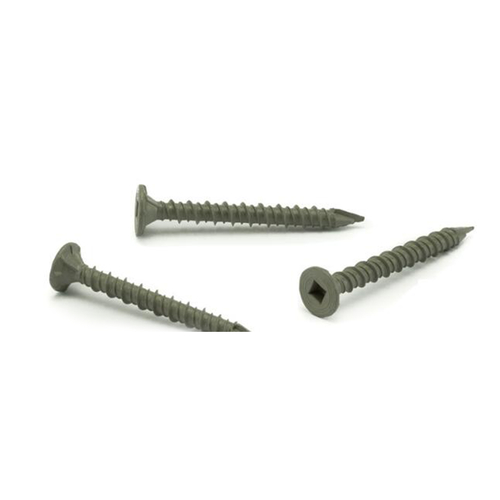
According to the purpose, the thread can be divided into two types: joint thread and drive thread.
In the cross-sectional view, the inner and outer threaded joints are drawn by external threads, and the rest are still represented by their respective drawings. The thick and thin solid lines of the large and small diameters of the inner and outer threads should be aligned separately.
Thread code labeling
The thread on the drawing needs to be marked with the specified thread code. The labeling format of the pipe thread is: feature code size code direction. Right-handed thread is omitted, left-handed with "LH"
Marking of thread marks
When the thread precision requirement is high, in addition to the thread code, the thread tolerance tape code and the thread screw length should be marked. The labeling format of the thread mark is: Thread code - thread tolerance band code (medium diameter, top diameter) - screw length
Description of the content of the label:
1) The tolerance band code is represented by a number plus a letter (the upper thread is used for upper thread and the lower thread is used for external thread), such as 7H, 6g, etc., it should be specially pointed out that 7H, 6g, etc. represent the thread tolerance, and H7, g6 represent the cylinder tolerance. Code.
2) The screw length is defined as three types: short (indicated by S), medium (indicated by N), and long (indicated by L). In general, the threaded length is not marked and the thread tolerance band is determined by the medium twist length (N). If necessary, the screw length code S or L can be added, such as "M20-5g6g-L". For special needs, indicate the value of the length of the screw, such as "M20-5g6g-30".


